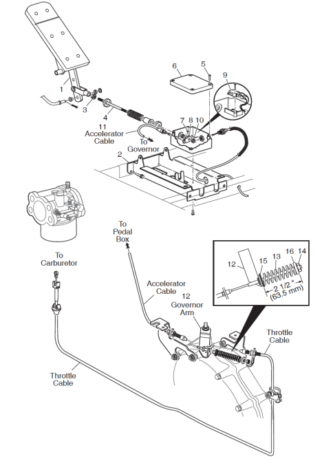
Speed Control Cables
ACCELERATOR, GOVERNOR AND CARBURETOR LINKAGE
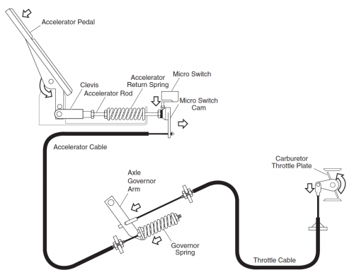
When the accelerator pedal is depressed, the accelerator rod moves towards the rear of the vehicle by overcoming the resistance of the accelerator return spring. As the accelerator pedal moves, the parking brake is released, the micro switch closes and activates the ignition circuit. The rear end of the accelerator rod is joined to the micro switch cam which connects to the accelerator cable. As the micro switch cam moves to the rear it pulls the accelerator cable, which pulls against the governor spring. When the accelerator cable pulls against the accelerator cable/governor spring, the spring compresses until it overcomes the resistance exerted by the governor mechanism. As the governor spring overcomes these forces, the governor arm moves and the motion is transferred through cable to the carburetor throttle plate.
Governor Operation
Until the vehicle reaches its governed speed, the vehicle will continue to accelerate in relation to the accelerator pedal position. When the governed speed is reached, the ground speed governor in the rear axle assembly operates against the governor spring and closes the carburetor until the correct governed speed is achieved. It is the force of the governor spring in response to accelerator pedal and governor arm position which controls the position of the carburetor throttle plate. This spring cushions sudden changes in throttle linkage position to provide smooth power transmission.
Governor Troubleshooting
Erratic acceleration and performance that does not include a notable increase in governed speed, may indicate the need for a linkage adjustment. Symptoms that include an increase in governed speed indicate:
• a possible governor failure within the rear axle
• worn components in the governor system
• improper adjustment of linkage system
SPEED CONTROL CABLES
Throttle Cable Removal
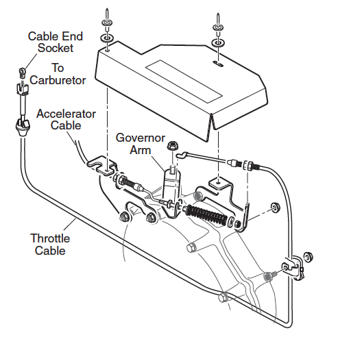
To remove the throttle cable socket from the carburetor throttle plate ball, pull down on the base of the connector to unsnap the end from the base. Remove cable end socket from ball. With a pair of pliers, pinch the bracket fitting to compress the sides sufficient to push cable fitting through throttle cable bracket. Remove governor cover by drilling out rivets. To remove the throttle cable from the governor, loosen the nuts securing the cable to the throttle cable bracket on the rear axle. Lift cable from bracket and remove cable end from governor arm. Loosen the four bolts securing engine guard under engine and remove cable.
To install the throttle cable, proceed in reverse order.
Throttle Cable Adjustment
To adjust the throttle cable, check to ensure carburetor throttle plate is fully closed and governor arm is rotated fully counter-clockwise. Position cable in the throttle cable bracket on rear axle so that the carburetor and governor remain as previously positioned with no tension, but minimal slack, on the cable and secure cable in position by tightening nuts on cable end.
Accelerator Cable Removal
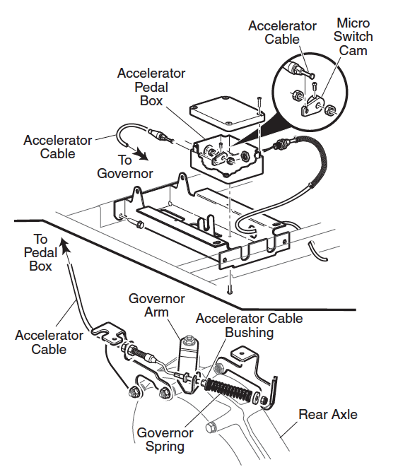
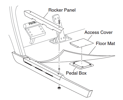
To access the micro switch, remove the rocker panel, lift the floor mat and remove the access cover from the floor. Remove the screws and cover from the pedal box. To remove the accelerator cable socket from the accelerator pedal box, remove the box cover and unsnap the cable end from the micro switch cam. With a pair of pliers, pinch the cable fitting to compress the sides sufficient to push cable fitting through accelerator pedal box. To remove the accelerator cable from the governor, loosen the nuts securing the cable to the accelerator cable bracket at the rear axle and lift cable from bracket. Remove end of cable from governor arm by using a pair of pliers to squeeze prongs on accelerator cable bushing.
To install the accelerator cable, proceed in reverse order.
Accelerator Cable Adjustment
To adjust the accelerator cable, position the cable in the accelerator cable bracket at the rear axle so that the throttle is fully closed while allowing 1″ travel at the top of the accelerator pedal. Once correctly positioned, tighten the cable securing nuts on the bracket.
PEDAL BOX ADJUSTMENTS
Accelerator Pedal Arm Adjustment
Lift front of vehicle. Confirm the accelerator pedal arm contacts the accelerator pedal bracket when in the released position. If there is no contact,loosen the jam nut and rotate the rod until contact is made.
Micro Switch Adjustment
When the system is in correct adjustment, the micro switch in the accelerator pedal box will click when the top of the accelerator pedal moves approximately 1/2″-5/8″ (13 – 16 mm). The accelerator cable (as seen at the rear axle) should have some slack present and not show any movement until after the micro switch clicks. To access the micro switch, remove the rocker panel, lift the floor mat and remove the access cover from the floor. Remove the screws and cover from the pedal box. Loosen the setscrew in cam using an 1/8″ Allen wrench. Loosen the jam nut and move the cam to adjust as needed. Adjust to permit 1/2″-5/8″ (13 – 16 mm) of accelerator pedal travel before the micro switch clicks.
Measure the distance at the top of the pedal with the pedal arm contacting the pedal bracket. Making sure the setscrew in the cam does not contact the micro switch actuator, tighten the setscrew to 45-55 in. lbs. (5-6 Nm) torque. Tighten jam nut to 10-11 ft. lbs (14-15 Nm) torque. Be sure the accelerator pedal moves smoothly and the accelerator cable pulls smoothly on the governor arm. Replace the cover on the pedal box. Tap lightly to set the cover before installing screws. Replace the access cover on the floor. Replace floormat and rocker panel.
GOVERNOR COMPRESSION SPRING
Adjustment
Pre-adjust the governor compression spring by rotating the nut until a dimension of 2 1/2″ (63.5mm) is achieved between the back of the accelerator
cable bushing and the outside of the cup washer. Tighten the nut. This dimension is a pre-adjustment and may be further adjusted after the road test.
Road Test
Test drive the vehicle and confirm that the compression spring adjustment results in the maximum governed speed specified. Determine speed by measuring the time it takes to travel a known set distance with vehicle at maximum speed. If the speed is not within the specified speed range, stop the vehicle and adjust the governor compression spring as described in procedure above. Repeat the test and adjustment until the factory recommended governed speed is achieved. Tightening the spring results in a speed increase while loosening it will result in a speed decrease.